
A remotely-tuned loop receiving antenna for LW and MW
If your only knowledge of suburban Maryland comes from seeing the movie The Blair Witch Project, you probably think Maryland is a vast wilderness where it would be easy to pick up longwave broadcasts without interference. Unfortunately, this is not really true. In fact, noise from power lines and computers in Maryland (especially networking equipment such as hubs and routers) often makes it difficult to hear anything in the LF band. Added to this is the inefficiency of the internal antennas of many receivers in the LF and VLF region. A loop antenna can solve both of these problems.
This article describes how to build a loop antenna for low frequency (LF) and medium wave (MW) reception with remote-controlled tuning. The antenna is extremely sensitive and can be built mostly from parts from old radios and tape recorders. Like all loop antennas, it is highly directional, which allows you to null out unwanted noise sources.
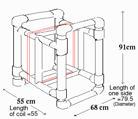
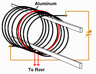
Diagram of the loop antenna. The main loop is 47 turns of wire (two loops are shown in red) around a frame made of 1-inch i.d. PVC tubing. Because PVC is more flexible than wood, the frame must be braced to prevent bending. The entire frame used four 10-foot lengths of PVC tubing, 8 elbows, and 8 tees. The four braces are cut with a circular notch at each end so they can be glued in place. Alternatively, by adding four additional tees and one cross, and making the antenna square instead of rectangular, you could arrange the braces in an X shape in the center as shown here.
Theory
Gain and Q
How big of a signal can you expect from a loop antenna? If you can
estimate the field strength, calculating the signal strength is easy.
The induced voltage E in a loop is
where E is in µV, e is the field strength in µV/m, N is the number of turns, A is area of the loop in square meters, theta is the angle between the plane of the antenna and the source, and λ is the wavelength in meters. This equation says that the voltage increases linearly with the number of turns, the area of the loop, and the frequency.
The loop and a capacitor form a tuned circuit. Adding more turns increases the inductance which limits the upper resonant frequency to which the loop can be tuned.
The radiation resistance of a multi-turn loop is given by
The Q of a multi-turn loop is
where fo = frequency,
Rr = radiation resistance of the loop (approx 200 Ω)
L is inductance
and
RL = ohmic losses.
The radiation efficiency at resonance is given by
This equation says that if the electrical resistance is 200 ohms, the signal strength will be cut in half.
Finally, the all important factor, the directional gain G is given by
where the directionality D for a square loop is approximately 1.7 or 2.3 dBi for a lossless antenna. This may seem low if you're used to microwave antennas, but remember the signal is also multiplied by the energy storage factor Q, which can be over 100. Thus a tuned loop antenna can produce quite a large signal despite its small size relative to the wavelength.
Antenna Dimensions
How big should the loop be to tune a given frequency range?
First consider the distributed capacitance of the loop itself.
For a square loop made of copper, this is approximately
where C is in pF, d is the ``diameter'' across the face of the loop in cm, and l is the length of the antenna (perpendicular to the wires) in centimeters.
Suppose the distributed capacitance comes to 100 pF. This capacitance is added (in parallel) to the capacitance of the tuning capacitor (20-420 pF). Thus our capacitance will range from 120 to 520 pF.
The inductance of a square loop in microhenrys is
where N is the number of turns, l
is the length of the coil in cm (i.e. the horizontal distance
between the start and the end of the loop), and d is the "diameter"
or length of one side in cm. This equation tells us that inductance
increases disproportionately as more turns are added, as shown in this
graph:
Effect of increasing the number of turns to a square loop of a fixed size 200, 100, 50, or 25 cm on a side. The inductance increases approximately with the square of d and is roughly proportional to the square of the number of turns. Antenna signal voltage also increases linearly with the number of turns and with the square of d.
The complicated equation above is the one recommended in the ARRL Antenna Book. However, for some combinations of parameters it gives a negative value for inductance. I found that in most cases this simpler equation for inductance is more accurate:

Using the formula or the graph above to obtain the inductance, we can use the formula for a resonant circuit

to calculate the resonant frequency, where f is the frequency in Hz, L is the inductance in henrys (H), and C is the capacitance in farads (F).
For the antenna described here, we have distributed capacitance = 35.7 pF, and L = 2217.7 µH. Given C = 20 to 420 pF, the antenna should be tunable from 167.6 to 436.2 kHz. In practice, I actually got 145 to 445 kHz (see below). This shows that the equations above are fairly close approximations.
If the distributed capacitance is ignored, the equation predicts that the antenna could be tuned from 177.1 to 811.6 kHz. This illustrates that the main effect of distributed capacitance is to reduce the upper frequency limit.
What would happen if you had a loop with only 1/4 as much inductance? Ignoring distributed capacitance, you would need four times as much capacitance to tune the same frequencies, i.e. 80-1680 pF. As the graph above illustrates, the way to get more inductance in an air coil is to add more wire.
Comparison with short dipole antenna. Because a loop antenna responds mostly to magnetic fields, it can have a noise advantage over antennas like the short dipole that respond mostly to the electric component. The reason for this is that at near-field distances close to the radiating source, the magnetic and electrical fields often differ significantly from each other. For example, if the emitter is a short circular current-carrying loop whose diameter is small in terms of wavelength (like the wiring in a house), the magnetic component (H_theta) of the EM field is weaker than the electric component (E_phi) when measured close to the emitter[1]. This means that, at distances below r/2πλ (where r=distance from the source), a loop antenna sensitive to the magnetic component will pick up proportionately less noise from nearby sources than a straight-wire antenna. However, if the noise emitter was a straight wire, or at intermediate distances from the noise emitter, the reverse would be true.
Although the above equations are usually fairly close for longwave antennas, they can be quite inaccurate for higher frequencies due to the difficulty in estimating the distributed capacitance. See the table at the bottom of this page for some actual measured values.
The area is the main factor in determining signal strength. The exact shape of the antenna is not important. It can be circular, triangular, or kumquat-shaped, as long as the inductance and the inside area are the same.
Materials
Structural material You have four options for structural material.
- PVC water pipe is inexpensive and easy to work with. PVC is
soft and can be glued together. The size is measured by the
inside diameter. Unfortunately, PVC is very flexible and you
need to use tubing at least an inch in diameter to create a
stable structure. As the antenna gets bigger, PVC becomes
less and less desirable because of its flexibility.
If you use PVC the antenna must be assembled outdoors, because PVC cement contains methyl ethyl ketone which is a neurotoxin that will destroy your brain cells.
Plumbers always use purple PVC primer before gluing PVC. This removes dirt and creates microscopic holes in the PVC that makes the connection stronger and more watertight when it is glued. It is not really necessary for your antenna unless you plan on using it underwater.
- Wood is low-tech but cheap. The antenna must be painted to prevent insects and mold from attacking it. For larger antennas, wood is preferable because of its greater rigidity.
- Copper or aluminum rod has a very low electrical resistance and would be mechanically rigid, but would also be more expensive and would still need bracing by some non-metallic components.
- Fiberglass
Tuning capacitor For remote tuning, you will need four NTE618 varactors, a 100 kΩ 10-turn potentiometer, and some 1 MΩ resistors.
Wire Large diameter copper or aluminum wire reduces the electrical resistance. Electrical resistance in the wire will lower the Q. The ideal wire would be solid insulated wire used for AC current, because its mechanical rigidity will reinforce the structure. However, 47 turns of this on a 2x3 frame is 470 feet which would be heavy. Litz wire is also sometimes recommended. In practice, as the equations above show, the type of wire makes little difference, as long as its total resistance is below about 100 ohms.
RJ45 jacks A 10BaseT flush mount single RJ45 jack with wall plate, 8 conductor, about $3.00 each http://www.trynci.com
BNC jacks and plugs
RG58 coaxial cable
Structural considerations
A larger antenna will give a stronger signal, at the cost of being harder to handle. If your receiver is insensitive, or you live in a quiet area, make the antenna bigger. In my tests I tried antennas up to 6x5 feet. This larger antenna produced such a strong signal that the receiver's S meter was at S8 to S9 from background noise, and the signal had to be attenuated when tuning through local stations.
The antenna must be at least one foot above the ground, otherwise the signal will be attenuated.
Antenna circuit
The antenna circuit is shown above. Only the resonating capacitor should be directly connected to the antenna. Connecting anything else, like the receiver, or adding any metallic elements, will distort the reception pattern and reduce the Q. A lower Q means weaker signal and broader tuning. The leads from the capacitor to the antenna should be as short as possible but this is not critical.
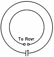
The coupling loop should be wound amidst the antenna turns, where the induced magnetic field is strongest. The optimal location can be found using a portable radio. The critical point is found at the position where the antenna tunes the sharpest. The largest signal is found at the edges of the antenna. The coupling coil does not need to be tuned.
Spacing between turns
Lower spacing between turns produces higher capacitative coupling between turns which lowers the Q and reduces the maximum frequency to which the antenna can be tuned. A minimum of 1 cm spacing is recommended.
Amplifier
A FET preamplifier could important if the antenna is outdoors and coupled by a long length of cable. However, with this antenna the background noise (mostly hiss, atmospheric noises, and unidentified tones) was so high that amplification was not necessary. In fact, the signal strength from atmospheric noise and local MW beacons was so high that at some wavelengths it was necessary to attenuate the signal to keep from damaging the receiver.
Attenuator
The 200 k volume control attenuates the signal to prevent strong stations from damaging the receiver.
Remote-controlled tuning
With a loop antenna, unless you tap into your receiver's tuning system, it's necessary to tune the antenna manually whenever you change frequencies. This is actually an advantage, because the antenna acts as a preselector. Strong local MW stations will easily overload most receivers if the antenna can receive them. In the LF band, this results in phantom AM and HF stations appearing all over the band. A tuned antenna can also make the bandwidth of your receiver narrower, by chopping off frequencies on one side of the signal. However, tuning the antenna is inconvenient if the antenna is mounted outdoors on top of a 20-foot mast. Thus, it's desirable to have a way of tuning the antenna remotely.
Intuitively, one would think that the antenna could be remotely tuned by connecting the tuning capacitor to a long wire. However, this doesn't work because such a wire would have its own capacitance which would make the loop impossible to tune, and would greatly reduce the upper frequency limit of the antenna.
Some people have tried to create simple remote antenna tuners by connecting a DC motor to the tuning capacitor. Unfortunately, this doesn't work very well either because it's necessary to switch the motor forward and backward and stop when you find the right position. What's needed is a motor that only rotates when you move the tuning knob, then automatically stops, in the same way as turning the capacitor by hand. A stepper motor does just this.
Unlike a regular motor, a stepper motor rotates a fixed angle when power is applied to one of the coils, and then stops. To rotate the motor, current is applied to each of the coils in sequence. If you use a multi-pole switch as a tuning knob to control a stepper motor, it's easy to tune the antenna remotely just as one would tune a radio. However, using a varactor is much more convenient.
Here is the type of circuit you would use for a Mitsumi M35SP-5 stepper motor.
This circuit will work, but you will hear faint clicks in the receiver as you rotate the switch, and the mechanical complexity means it's not as reliable as a varactor circuit. I measured a Q of 144 using a mechanical 10-365 pF plate capacitor from an old AM radio with this circuit.
Remote tuning using the NTE618 varactor
In the past 20 years, silicon tuning diodes have almost completely replaced plate capacitors in low-power applications, because diodes can be tuned by varying the voltage instead of by turning a mechanical knob. They are also much smaller and cheaper and have comparable performance. The NTE618, for example, has a capacitance ratio of 15.5, which means it can (in principle) tune frequencies over 3.9-fold range.
The tuning range of a capacitor is proportional to the square root
of the ratio between its maximum and minimum capacitance. This
means that it would be very difficult to tune a single antenna
over a wide range without switching elements in and out. For example,
ignoring fixed stray capacitance, to tune from 150 to 2 MHz you would
need a varactor with a maximum/minimum capacitance ratio of 178.
A simple solution is to add a bank of switches on the antenna to add
more capacitors when needed.
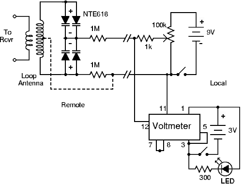
LF antenna circuit using NTE618 varactor. Also shown are connections for a Datel DMS-30PC voltmeter.
NTE618
The circuit above was connected to the controller with 25 feet of Cat-3 cable and the antenna secondary was connected to a receiver with 25 feet of RG-58 coaxial cable. The Q was measured to be 211 at 170 kHz, significantly better than the plate capacitor circuit.
Notes on the remote tuning circuit:
- The capacitance of a diode decreases as the potential is increased, from about 420 pF at 1.2 V to 20 pF at 8 volts.
- The diode will break down if more than 16V are applied. In practice, no change in capacitance was observed when the potential was raised above 9 volts. Hence I used a 9V battery as the voltage source. A 10-turn wirewound 100k potentiometer acted as a voltage divider.
- The 1k resistor protects the potentiometer in case the output is accidentally shorted.
- It is necessary to use varactor diodes in pairs, otherwise the voltage received in the antenna will change the capacitance, which leads to distortion and nonlinear effects. However, this reduces the capacitance by half. To compensate for this, I used two diodes in parallel to bring the overall maximum capacitance back up to 420 pF.
- It is critical to keep the LC circuit as isolated as possible. If you connect a preamplifier to the primary loop, the preamp must have a very high impedance. Interference from the power supply must also be avoided. If the power supply were connected directly to the LC circuit, stray capacitance from the lines would disturb the antenna resonance. The signal could also be shorted out by a low impedance power supply. The symptoms would be a low Q, weak signal, and broad tuning. This is avoided in the circuit above by placing two 1MΩ resistors on the remote side. A larger resistor, up to 10MΩ, will also work.
- The 1MΩ resistors also serve to limit the amount of current that could flow through the diode, acting as a safety measure in case the battery is accidentally inserted backwards.
- If distortion is observed with strong stations, make the center of the loop more negative as shown in the dotted line.
- The Datel DMS-30PC voltmeter is sold by Mouser as a complete unit and is very easy to hook up. However, its high intensity blue LED display uses a lot of current. I used two D cells to run it at a reduced intensity. If I built another one, I would probably use a liquid crystal display.
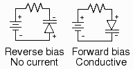
General notes on varactor diodes:
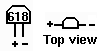
- Varactor diodes are always operated under reverse
bias conditions as shown below. Under these conditions
there is no current flow. This makes sense for a capacitor,
which is not supposed to pass direct current.
These diodes are not as susceptible to damage by reverse
current as LEDs are, but they will not work when operated
with forward bias.
- The diagram that is supplied with the diode is ambiguous concerning the polarity of the diode. I had to use the old voltmeter and battery test to identify which end is the cathode. Looking at the "front" of the diode, with the electrodes pointing down, the electrode under the '8' is the cathode (negative) side and the anode (positive) is on the left.
When this simple circuit was connected to the loop antenna described above, the antenna could be tuned from 145 to 445 kHz. No preamplifier was needed, because the background noise and atmospheric noise were well above the receiver's noise floor, ranging from S5 to S6. (I told you Maryland was noisy). This compares with mostly receiver noise at S0-S1 using the receiver's built-in ferrite loop.
Since many receivers use a similar varactor circuit, you could in principle tap into the receiver's tuning system to obtain the tuning potential for the antenna, thereby avoiding the need to manually tune the antenna. I did not try this.
Coupling to a receiver
The antenna captures magnetic (and some electrical) energy from the area encompassed by the coil and re-radiates it. This means if you put a radio within about 6 feet of the antenna, the receiver's ferrite loop will pick up the signal from the antenna by induction. Placing the radio directly inside the loop antenna gives the strongest signal.
In my tests with a Sony ICF-2010, the 3-turn secondary coil also gave a strong signal when connected directly to the Sony's external antenna input. However, it was not as strong as placing the radio inside the antenna. I suspected that this may have been caused by an impedance mismatch; however, a variety of transformers had no effect, so I drilled a hole in the receiver and soldered connections for a new external antenna jack in parallel with the radio's ferrite loop onto the circuit board. The connections were made at the "N" in the upper right corner and above the "3" at D303. With this modification, it's also necessary to disconnect the internal ferrite loop. The easiest way to do this is to insert a non-metallic object such as a Q-tip into the External Antenna plug.
A better signal can be obtained by connecting the loop antenna at the "N" in the upper right corner and above the "2" at Q302. This gave a tremendous increase in signal strength. However, this connection makes the antenna susceptible to image problems in the receiver, with AM broadcast stations sometimes showing up everywhere. I recommend trying both and switching from one to the other if you start picking up images. For the Sony ICF-2010, I also strongly recommend installing four protective diodes to prevent damaging the front-end FET. The procedure for doing this can be found in many places on the Web.
Warning: Doing this to your receiver is risky. Modern receivers are practically miniature computers. If you touch the wrong place on the circuit board without being grounded, or connect the wrong two points together electrically, the radio could go permanently dead.
Performance
As mentioned earlier, the antenna had a Q of about 211. This means it produces a lot of signal, but also has a narrow bandwidth. For instance, when tuned to 158 kHz, the antenna only responds to signals between about 155 and 161 kHz.
The loop antenna gave a tremendous increase in signal. Signals that were marginally readable with the Sony ICF-2010's internal ferrite antenna pegged the meter with the loop antenna; others that were undetectable were clearly readable. Instead of receiver noise, the entire band was filled with man-made background signals of one sort or another, a combination of hiss-like noises and tones, at S5. This is in contrast to the background with the Sony's internal ferrite loop antenna, which could only detect the strongest signals, and for which the background was S0 or S1.
Interference from computers was not a major problem, as long as the computer was more than 25 feet away from the antenna. Of course, if anyone in the neighborhood turns on any halogen lamps (which generally use SCRs in their power supplies) the radio goes crazy with power line noise that radiates from every electrical wire in the building that contains the appliance. If the building is far enough away, it's usually possible to null out this noise by rotating the antenna. Ideally, however, the antenna should be mounted outdoors as far away from any buildings as possible. The S/N ratio improved markedly when the neighborhood electrical power was off.
Even indoors in the basement, the loop antenna was far superior to an attic random wire antenna and an active antenna located outside at the far end of my fence. I can only speculate what signals could be received if I placed this loop antenna on my roof. However, that's not going to happen anytime soon.
When the antenna is outdoors, I keep it covered with a gray plastic barbecue cover with the words "Kiss the cook" printed on it, so that neighbors think it is a barbecue. Another listener disguised their antenna as a Christmas tree light holder.
The main problem with the antenna was that the signal strength from
nearby stations was too high. As mentioned, the background noise,
which consisted of atmospheric noises and random unidentified
man-made bleeps, kept the meter at S5. Nearby signals, such as
signals from Washington, D.C., pegged the meter at S10. Clearly
amplification is not needed for this antenna. It's recommended
to use the attenuator when tuning through strong stations.
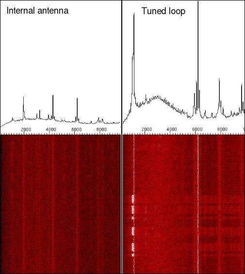
Sonograms comparing a beacon received using a Sony ICF-2010 at 323 kHz using the internal loopstick only (left) and the tuned loop (right).
Calibration
The resonant frequency is related to the voltage as shown in the graph below. The blue curve is for the larger antenna described above. Results from a smaller version of the loop antenna, using six varactors to give a range of 30 to 630 pF, are shown in black. The curve begins to level off at higher voltages as the varactors become saturated.
Click here for an image of the small loop antenna and controller used in this test.
By piling on more varactors and fixed capacitors, I was able to get the larger antenna to resonate as low as 44 kHz, easily picking up a clean signal from WWVB at 60 kHz. By contrast, with a variety of other antennas, only noise and intermodulation products could be heard.
Stations received
Most MW and LW beacons are only 25 watts, so long distance reception is unlikely. From my location in suburban Maryland using a Sony 2010, it was possible to read about 30 or 40 NDBs (nondirectional aeronautical beacons) during the daytime in the summer, from up to 500 miles away. At night, it was possible to hear beacons as far away as Puerto Rico, and occasionally detect European LW broadcasts. The fact that the antenna is tuned is a big advantage here, because it leaves no doubt that the station is real. It's easy to be fooled by images of HF and BCB stations appearing in the LF region.
Other antennas
An attempt to make an antenna using a single loop made from four 72-inch pieces of aluminum screen frame material was unsuccessful. The antenna had an embarrassingly high Q, but because of its low inductance it resonated in the HF band and could only be tuned from 2500 to 4100 kHz.
A more successful antenna was made from three 40-foot lengths of aluminum grounding wire. This wire is sold in 8-inch diameter coils, so I made the antenna the shape of a long helix, 8 inches in diameter and about six feet long. This is too short to reach the LF region, but with a six-varactor remote tuning circuit similar to that shown above, this antenna could be tuned from about 500 to 2400 kHz, easily covering the entire MW broadcast band. Because of its small area, the antenna output was not as high as the larger loop antenna; however, unlike the large loop antenna, this coil antenna was small enough to mount outside, away from interference, without incurring the wrath of the local Homeowner's Association, and gave an excellent S/N ratio. However, to reach 150 kHz with this antenna, you would need at least three times as much aluminum wire (or a big honking capacitor).
Helical tuned loop antenna for MW Tuned loop antenna for HF
Extending the same principle to higher frequencies, we end up with a single aluminum loop, 6 feet in diameter (see figure above). A second loop, 4 feet in diameter, picks up the signal and sends it to a preamplifier or a receiver. With a switchable fixed capacitor in parallel with a 15-365 pF capacitor, this antenna could be tuned from 1700 kHz to about 7700 kHz. A series of such loops of different sizes could probably cover the entire HF band. Because it is a tuned antenna, it produces a much stronger signal than the same length of wire in a straight line. The tuning also eliminated interference from MW stations in the problematic 160 meter band. However, because of its conspicuous shape, it couldn't be mounted outside and therefore also picked up a fair amount of noise from house wiring.
[1] R.C. Johnson, Antenna Engineering Handbook, pp. 2-2 to 2-6.
Update (Feb. 11, 2007)
Here are some actual measurements for an air loop antenna with the following specifications:Length of one side = 62 cm
Overall length of coil = 62 cm
No. of turns = 15
| Capacitance (pF) | Frequency (kHz) |
| 4.6 | 1720 |
| 9 | 1557 |
| 15 | 1458 |
| 112 | 665 |
| 225 | 475 |
| 365 | 354 |
Update (May 6, 2008)
I finally got my hands on a big honking air variable capacitor and a fairly accurate capacitance meter. I measured the relationship between capacitance and resonant frequency of a small antenna (L=16, d=30.6, n=55.75 turns) and a large antenna (L=54, d=79.5, n=63 turns). The figure below shows a curve that roughly follows frequency proportional to 1 / sqrt(capacitance), as expected. The measured resonance frequencies are a fairly close match to the calculated ones.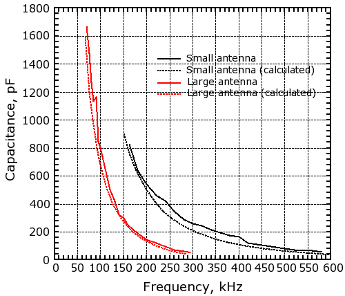
Loop calculator source code
Back