Build an Air Variable Capacitor
Introduction
 ariable capacitors are useful in a lot of situations. But adjustable plate
capacitors bigger than 1000 pF are difficult to find, and those that are
available tend to be inconveniently large. There are several good tutorials
on the Internet for building rotatable air variable capacitors like those
found in old AM radios. However, because it's difficult to cut sheet metal
into a curved shape while keeping it perfectly flat, the plates have to
be kept far apart, which gives them a very low capacitance. The round shape
also tends to be bulky. I woke up one day and decided to invent a new
design that would be (1) compact and (2) have a high capacitance
(preferably above 5 nF). It should be easy to construct using readily
available parts. Should be easy, I thought. Next time maybe I'll know better.
| Element | Aluminum 6010 | Aluminum 6011 |
|---|---|---|
| Cu | 0.15-0.60 | 0.40-0.90 |
| Mg | 0.6-1.0 | 0.6-1.2 |
| Si | 0.8-1.2 | 0.6-1.2 |
| Fe | 0.50 | 1.00 |
| Mn | 0.20-0.80 | 0.80 |
| Ti | 0.10 | 0.20 |
| Cr | 0.10 | 0.30 |
| Zn | 0.25 | 1.50 |
The idea was to make the plates from the aluminum in a Venetian miniblind, and use an immobilized screw system to convert rotation into translational movement. As the table above shows, Venetian blinds use a high-silicon containing aluminum alloy such as 6010 or 6011. This makes them much springier than ordinary aluminum, allowing them to be easily cut with scissors or a paper cutter without deforming their overall shape.
Theory
As shown in the equation below, the capacitance of a flat plate capacitor depends on the area A, the number of plates (n), and the relative permittivity (εr), also known as dielectric constant, of the medium between the plates. Capacitance is also inversely proportional to the distance d between the plates, which means that the biggest improvement can be made by moving the plates closer together. The equation for a capacitor is

where dimensions are all in meters.
This is where the great idea of using Venetian blinds comes in. The
paint coating on my old Venetian blinds was about 10 microns (0.01 mm)
thick. The distance between two painted plates would then be only 20
microns, making the denominator really small. The paint that separates
the plates would also have a dielectric constant much higher than air,
increasing the capacitance by another 3 to 4-fold.
Not much to the theory, actually.
Mechanical details
The mechanical part turned out to be the easiest. A screw is threaded through a large Plexiglas or Delrin (polyacetal) nut that is prevented from rotating by the plates and by two height-adjusting screws. When the lead screw rotates, rotational motion is converted to linear motion which pulls the capacitor plates farther apart.
For the lead screw, take a five-inch piece of 8-32 threaded steel rod and grind the threads on both ends, leaving a 10.5 cm threaded area as shown in the diagram below. Grind a flat area on the front end for a knob. Cut two 1-5/8" wide pieces of 1/16" x 1 inch angle aluminum for the front and back. Drill holes just big enough for the thread-free part of the lead screw to fit through. The rod must fit tightly in those holes. Mount the aluminum angles underneath the plastic body using countersunk holes for three 4-40 screws in the front. In the back, use two 1-1/4" long 4-40 screws to hold the aluminum angle to the body. They will also hold the plates.
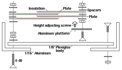
Side view showing four plates.
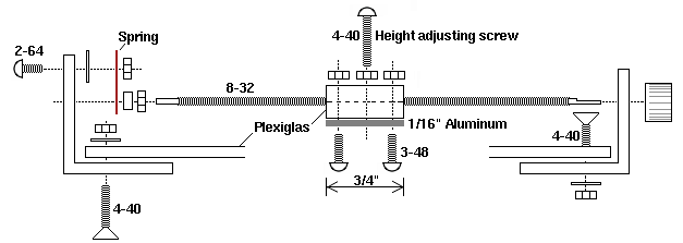
The other side, viewed from same orientation.
Cut a 3/8 x 5/8 x 3/4" piece of Plexiglas or Delrin and tap an 8-32 hole through it lengthwise to make a square plastic nut. When drilling Plexiglas, drill very slowly, otherwise it will heat up, melt, seize, and possibly crack. If you use metal instead, you will need to find a way to insulate the aluminum plate from the main screw, so the capacitor is not shorted out.
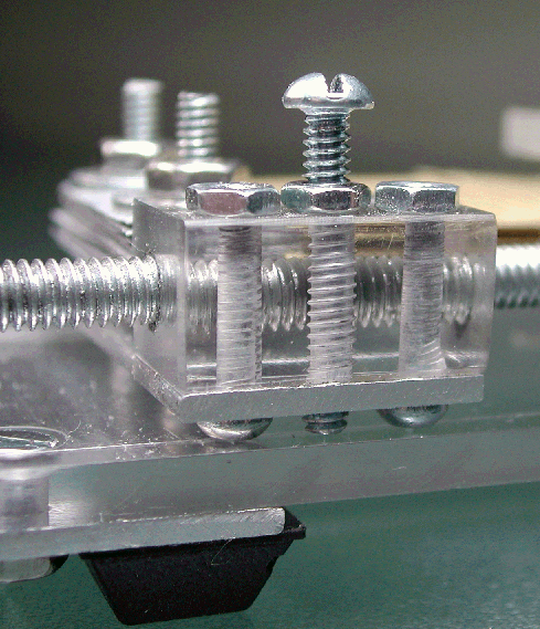
Closeup of nut assembly. A gear and rack system or ball screw system could also have been used.
Attach the 1-1/2 x 3/4 x 1/16" aluminum platform to the plastic nut using two 3-48 screws. Mount two one-inch long 4-40 screws on the aluminum platform so that they are parallel to the two screws in the back. These will hold the front plates. Tap the plastic nut and the aluminum platform and add a couple of height adjusting screws as shown. These prevent the nut from rotating as the knob is turned.
The spring
A spring is essential in order to prevent play in the main screw. Cut a rectangular flat spring from spring metal. Rather than trying to bend it, which will only fatigue the spring, leave it flat and drill two holes in it. Use a 2-56 screw and nut to attach it to the back. The spring in the photo below was from an old wind-up clock that I took apart in 1967. That spring sat around for 41 years before I finally found a use for it. An alternative source of spring metal is those blue metal bands that are used in shipping. Once a piece of this is cut to the final shape, it can be heated with a torch to harden it into a spring.
To drill a hole in the spring, place a block of aluminum underneath and clamp the spring to it.
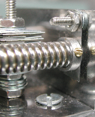
Closeup of spring.
Next take an 8-32 nut and grind it perfectly flat on one side. Grind the edges off to make it round. Then fix it in place on the main screw by drilling a small hole and screwing a 00-90 screw through it, or by jamming it against a second nut, so it extends about 1 mm away from the start of the threads. This provides a flat surface to press against the spring. If this is not present, the point where the screw threads start will always be slightly uneven, and the screw will move forward and backward slightly as it is turned.
The finished screw should turn evenly and have no back-and-forth or front-and-back play, and the plastic nut should not rotate when the knob is turned.
The plates
Unfortunately, my great idea of using the paint from the painted Venetian blinds to separate the plates didn't work as planned. If I simply cut the plates with scissors, the edges were never flat enough, and the uninsulated edges would contact each other. So I had to strip the paint off and coat them. But there's a trick to get around this.
The stripping can be done using ordinary paint stripper, which contains methylene chloride. Be sure to do this outdoors or under a fume hood, as this stuff is highly toxic. Other chlorinated solvents, like chloroform, will also work. Solvents like lacquer thinner, turpentine, isopropanol, hexane, acetone, and ethanol do not work.
Cut the strips last, once the mechanism is finished. The strips must overlap by at least 1 mm at the widest setting. Cut a few extra ones, because when you drill the hole, the top and bottom one will probably get all crunked. Clamp the strips together and slowly drill one hole through all of them simultaneously. Then screw them together through the first hole before drilling the second one. To get rid of the curvature, flatten the pieces by gently rolling them against a cylindrical object like the axle of an empty wire spool.
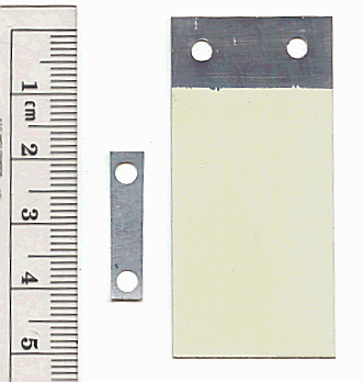
Spacer and plate.
Next, make a large number of spacers from a stripped piece of aluminum. Make them oversized so it's easier to drill the holes. Drill the holes in the same way as for the plates, then cut the spacers to the correct size with a pair of scissors.
When I started this project, I hoped the paint on the Venetian blinds would be sufficient to keep them apart. This turned out not to be the case. If you make the plates from the inside portion of a vane, it's necessary to add more insulation to prevent the plates from short-circuiting. This can be done by adding thin plastic sheets between the plates, or by anodizing the plates. Spray-painting the edges did not work very well.
Another trick is to use only the ends of the vanes. These ends are already flat, so there's no need to strip and coat them. Plus, they are rounded, which reduces arcing if you use the capacitor at a high voltage.
Method 1: Anodizing
Anodizing is probably the best way to insulate the plates. Anodizing leaves a hard black or gold coating that doesn't conduct electricity. The coating is thinner than a plastic sheet (5 to 18 microns, or 0.005 to 0.018 mm thick, compared to at least 0.025 mm for 1 mil plastic). This means you will get a much better capacitor.
Here is the procedure for anodizing. Chromate anodizing works better than plain sulfuric acid anodizing for this type of aluminum.
- Strip the paint by soaking the aluminum strips for 5 min in chloroform.
- Wash the strips again in chloroform and wipe any remaining paint with a paper towel. Wear gloves and avoid touching the surface of the plate.
- Screw the plates together, separating them with metal washers. Connect the plates to the (+) terminal of a DC power supply capable of producing several amperes at 15 volts. One amp is enough to anodize two square inches in about 30 min. Less current will take proportionally longer time.
- Connect the (-) terminal to a piece of aluminum. Put both electrodes in a 100 ml beaker, keeping the end with the holes out of the solution. Make sure that only aluminum is in contact with the solution.
- Fill the beaker with 15% sulfuric acid containing 1% potassium dichromate. Place the beaker in a larger water-filled container to absorb the heat.
- Apply sufficient current to create about 15V across the terminals. Hydrogen and oxygen gas will be produced, and the solution will heat up. It must be at or slightly below room temperature for best results.
- Check the resistance of the coating, then rinse and seal the pores in the aluminum oxide coating by boiling in water.
- Neutralize the chromate and dispose as toxic waste.
One advantage of anodizing is the high dielectric constant of aluminum oxide (9.34), which is higher than vinyl (3.5-4.5), polypropylene (1.5), air (1.0006), and even glass (4-7). Since capacitance is proportional to the dielectric constant, anodized aluminum should theoretically have 9 times higher capacitance than an air capacitor.
Before installing the plates, add washers if necessary so that both rows of plates are exactly the same height. Then add one plate separated by two spacers on each side, alternating sides so the plates are interleaved. Add another No. 4 washer on top and screw in place. Check for shorts.
Method 2: Plastic sheets
Alternatively, you can use a plastic sheet to separate the plates. This is the easiest and most reliable method if a high capacitance isn't needed. The best material is 3M 9457 Adhesive Transfer Tape, which is 1 mil (0.0254 mm) thick. Some types of packing tape are also 1 mil thick. Completely strip the paint from the plates and stick one piece of the tape on top of each plate, making sure to avoid bubbles. The tape should extend about 1/2 mm from the edge. Leave the part of the plate near the holes uncovered. Put tape only on one side of the plate. Install the plates, using two spacers between each plate, and make sure the plates are interleaved (see diagram). Add a No. 4 washer on top and screw in place. With 25 plates total, this capacitor could be adjusted from 90 to 4500 pF.
Method 3: Use the ends
An even easier way is to use only the left and right ends of the Venetian blind to make your plates. Drill the holes on the side away from the end of the vane. Then dip the side with the holes in paint stripper to remove the outermost 7 millimeters of paint. The rounded outer edges are sufficiently flat that there's no danger of a short circuit as long as the plates are flat, clean, and have a uniform shape. If short circuiting should occur, coat the edges of the plates using a Magic Marker to insulate them. Although this method of making plates is easy, it has two disadvantages: first, you will use eight vanes from your Venetian blind instead of only two or three; and second, the uninsulated edges are fairly close together, so high voltage could still cause arcing. For receiving antenna applications, this is not a problem. The paint is only about ten microns thick, so you can get a high capacitance with only a few plates. Two spacers per plate is sufficient.

Side view showing plates.
With 16 plates, this capacitor could be adjusted from 90 to 3400 pF. By increasing the number of plates to 24 and reducing the total number of spacers from 48 to 36, it was possible to increase the maximum capacity to 8400 pF. However, it is not recommended to use fewer than two spacers per plate, because it causes the plates to bend.
Summary
The Venetian blind variable capacitor has several advantages over the conventional type:
- It is very easy to get a very high capacitance and a good high/low capacitance ratio. With only 24 plates, it had about 4500 pF. It had a minimum of about 90 pF, for a ratio of 50:1. This compares with only 15-365 pF for commercial variable capacitors of roughly the same size. If you only need 360 pF, three or four plates should be sufficient (or, you could make the plates smaller).
- Multiple turns eliminates need for gear reduction and allows highly accurate tuning. No expensive gear reduction system is needed.
- It is easy to add or remove plates. More plates can be slapped on with four screws for higher capacitance. This makes it easy to try different designs or coating methods.
- Plastic nut provides smooth, silent rotation.
- It's more compact and fewer plates than a conventional rotating design because the coated plates allow a closer spacing. The overall size was 4.5 x 1.75 x 1 inch. With a little effort, the height could easily be reduced to half of that, or even less. The design is also potentially more precise than the rotating plate design, making it useful for other applications.
- No worries about plates bending and touching each other because they are already touching each other.
- Easier to construct because the plates are rectangular instead of circular. Venetian blinds can be cut with scissors.
- Requires less torque to turn than a geared rotating design. This makes it easy to attach a motor for remote control.
- The knob turns in the direction you would expect: clockwise for lower capacitance and higher frequency.
There are also some disadvantages:
- More rotations are required to cover the entire range.
- For high voltage applications, the plates have to be stripped and anodized or coated with insulating tape. Anodizing is a fair amount of work.
- This turned out to be a lot more work than I originally thought.
Improved design
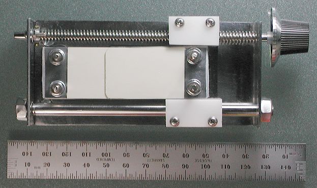
Improved version of capacitor
To get better precision, an Acme thread should be used, and the moving platform should be supported on both sides. I made a 1/4"-16 Acme tap and used it to create a nut out of Delrin. On the opposite side, there is another piece of Delrin that slides freely over a 1/4" polished steel rod. Screw threads are cut on each end of the rod to hold it in place. I also used 1/16" steel instead of aluminum. With 20 plates on each side (40 plates total), the capacitance was 350-6530 pF. With 10 plates on each side (20 plates total), the capacitance was 190-3300 pF.
