
A High-Gain 2.4 GHz Helix Antenna
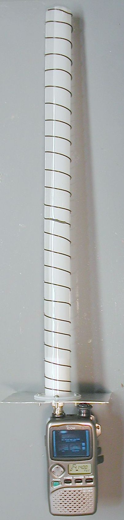
At microwave frequencies, many factors that are unimportant at lower frequencies influence how well an antenna works. These factors include wire diameter, type of insulation, and the dielectric of the support. For helix antennas, another critical component is the innocuous-looking reflector plate, without which the antenna will barely function. By a combination of trial and error and luck, I found a design that is easy to construct, compact, and works well. When connected to an Icom R-3 as shown in the photograph below, the R3 (which is normally rather deaf at 2.4 GHz) became highly sensitive. The directional gain was measured to be 16 dBi. This antenna is only about 18 inches long and can easily be constructed from ordinary, inexpensive parts. It is useful for extending the range of small 2.4 GHz wireless cameras and for reducing interference of Wi-fi networking signals.
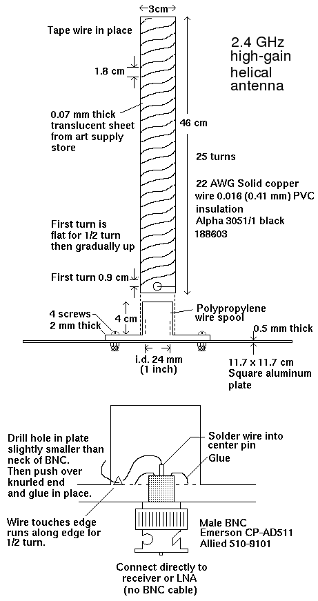
It is often said that the dimensions of a helix antenna are not critical. However, this can be misleading; even at 2.4 GHz, a difference of a few millimeters makes the difference between an antenna that works well and one that does not. In the diagram below, the number of turns and length may be increased and the antenna will still work, provided that the spacing between turns is not changed. However, many of the other specifications and sizes are critical. If changed, the antenna will work poorly or not at all.
Construction Details
Cut one end off a plastic (polypropylene) wire spool leaving a T-shape 4 cm long and 30 mm in diameter. Create a 46 cm long cylinder by wrapping 0.07 mm thick acetate sheet (available from arts supply stores) around the T-shaped wire spool 1 1/2 to 2 times. Use wide packaging tape to fix the acetate in a cylindrical shape (I used Scotch 3750 DD tape). Solder the wire to the center pin of a BNC plug and wrap it around the acetate sheet as shown.
Click on images to enlarge
Notes on the 2.4 GHz Helix Antenna
- The wire should be 22 gauge PVC insulated hookup wire. Using aluminum wire or heavy, uninsulated copper wire gave a much poorer performance.
- The dielectric of the cylindrical support is critical. Substituting PVC tubing or using an air coil did not work at all (that is, it was worse than a monopole antenna).
- The reflector plate is also critical. If it is too big or too small, the efficiency will be greatly reduced. If steel 1x1 cm mesh of the same size was substituted for aluminum plate, there was almost no signal. The plate must be solid aluminum and as flat as possible. Even small deviations cause the beam pattern to go off at weird angles.
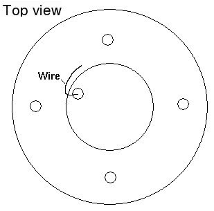
- The point where the wire connects to the BNC connector is also critical. The geometry of the wire acts as a transformer to match the helix to the 50 Ω BNC connector. (Be sure to use a 50 Ω BNC connector, and not a 75 Ω connector). If the wire were simply attached in a straight line, it would create an impedance mismatch that could cause significant signal loss. The wire touches the bottom of the plastic wire spool and travels along the inside corner for 1/2 turn. It is threaded into the inside of the spool. The BNC connector is not centered, but is about 1/4 of the i.d. of the spool from the edge, as shown in the top view.
- The wire is soldered to the center pin of the BNC connector. At this point, the wire actually loops a small distance farther away from the aluminum plate.
- The shell of the BNC connector makes electrical contact with the aluminum plate. It is held in place by friction and a small amount of epoxy glue (J-B Weld).
- Ideally, the BNC connector should be connected directly to the receiver or low-noise amplifier (LNA), with no intervening cable. Even a short cable can cause the loss of several decibels.
- The aluminum plate is square (not round) and is not bent into a cup shape as is done on some other antennas. Cut the plate with a saw, not shears, to avoid warping it.
- The aluminum plate must not be connected to any other metal objects.
Antenna Pattern
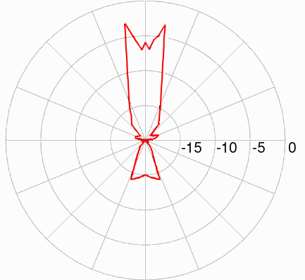
I tested the antenna by connecting it to a 2.4 GHz signal source and measuring the pattern using a spectrum analyzer in an open field relatively free of objects that could reflect the microwave signal. The directional gain was measured to be 16 dBi. In comparison, a monopole (whip) has a gain of only 4.8 dBi.
The reception pattern is shown in the figure below. The pattern was somewhat unusual in shape, with a slight decrease in signal when the antenna was pointed directly at the receiver. This was probably caused by the use of a flat plate instead of a cup. In the far-field, doubling the distance decreases the signal strength by one S unit, or 6.021 dB. In other words, every 6.021 dB of gain represents a doubling of the distance for equal signal strength. Therefore, you can roughly expect 6.35/1.74 = 3.6 times as much range with this antenna as a monopole, using the formula:
The improvement indoors for any directional antenna is usually
less impressive than as shown here, because of the large number
of reflections. Even nonmetallic surfaces such as walls can produce
reflections.
Low Noise Amplifiers
If the antenna is separated from the receiver by a cable, a low-noise amplifier (LNA) may be needed to compensate for cable loss.
The most cost-effective solution is to build an LNA yourself. Agilent makes a series of inexpensive broadband GaAs LNA MMICs, such as the MGA-61563, which has a noise figure of 1.2 dB at 2 GHz, and only requires a small number of external components. It is available from large, reputable vendors such as Newark. However, a certain amount of knowledge of microwave engineering is needed to assemble these units. Another excellent vendor is Mini-Kits, a small but reliable Australian company that sells LNA kits. Although they're oriented toward hobbyists, their ceramic PCBs are nicely laid out, making them valuable tools for learning microstrip construction techniques.
However, with one of their kits, I had to modify the circuit slightly to get it to work.
Other reputable vendors are Mini-Circuits , DJM Electronics , Downeast Microwave , and Kuhne Electronic GmBH . A few other vendors were less reliable.
Obviously, something more sophisticated than a simple amplifier would be needed for two-way communication or network use. A wireless network card or router sends out a burst of signals as soon as it's turned on. This would probably fry any LNA that was directly connected to the network card.
Other Antennas
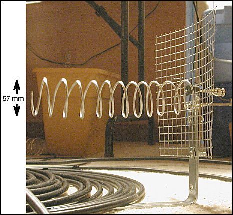
Here is an antenna that looks like it should work, but does not,
even at 1.67 GHz where the equations say it should be optimal. The
helix is made of aluminum grounding wire. The reflecting plate is
welded steel grid from a hardware store. The aluminum wire is just
the right diameter to fit into an RCA-to-BNC adapter. This antenna
performed worse than no antenna at all!
Conclusion
This compact, medium- to high-gain antenna is well-suited for improving
signal strength in the 2.4-2.5 GHz ISM band. Because helix antennas have
a relatively wide bandwidth, the antenna is also very effective at nearby
frequencies. If necessary, an SMA connector could be substituted for the
BNC plug to connect the antenna to a wireless router or network card.
Back